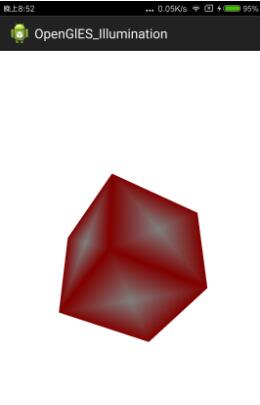
为了演示光照效果,在前面学习过的内容基础上我们首先创建一个立方体,同时为了看起来直观一些,这个立方体每个面采用中心为白色,周围红色的渐变方案,不然看上去同样的颜色混在一起,看不出来是否是立方体。并且添加上转动旋转功能,这样转动起来立体感更强一些。
一个立方体
立方体类Rectangle.java
public class Rectangle {
  private FloatBuffer mVertexBuffer;
  private int mProgram;
  private int mPositionHandle;
  private int muMVPMatrixHandle;
  private int mColorHandle;

  public Rectangle(float r) {
    initVetexData(r);
  }
  public void initVetexData(float i) {
    float vertices[] = new float[] {
        // 顶点   颜色
        //前面
         0, 0, 1, 1,1,1,0,
         1, 1, 1, 1,0,0,0,
        -1, 1, 1, 1,0,0,0,
         0, 0, 1, 1,1,1,0,
        -1, 1, 1, 1,0,0,0,
        -1,-1, 1, 1,0,0,0,
         0, 0, 1, 1,1,1,0,
        -1,-1, 1, 1,0,0,0,
         1,-1, 1, 1,0,0,0,
         0, 0, 1, 1,1,1,0,
         1,-1, 1, 1,0,0,0,
         1, 1, 1, 1,0,0,0,
         //后面
         0, 0,-1, 1,1,1,0,
         1, 1,-1, 1,0,0,0,
         1,-1,-1, 1,0,0,0,
         0, 0,-1, 1,1,1,0,
         1,-1,-1, 1,0,0,0,
        -1,-1,-1, 1,0,0,0,
         0, 0,-1, 1,1,1,0,
        -1,-1,-1, 1,0,0,0,
        -1, 1,-1, 1,0,0,0,
         0, 0,-1, 1,1,1,0,
        -1, 1,-1, 1,0,0,0,
         1, 1,-1, 1,0,0,0,
        //左面
        -1, 0, 0, 1,1,1,0,
        -1, 1, 1, 1,0,0,0,
        -1, 1,-1, 1,0,0,0,
        -1, 0, 0, 1,1,1,0,
        -1, 1,-1, 1,0,0,0,
        -1,-1,-1, 1,0,0,0,
        -1, 0, 0, 1,1,1,0,
        -1,-1,-1, 1,0,0,0,
        -1,-1, 1, 1,0,0,0,
        -1, 0, 0, 1,1,1,0,
        -1,-1, 1, 1,0,0,0,
        -1, 1, 1, 1,0,0,0,
        //右面
         1, 0, 0, 1,1,1,0,
         1, 1, 1, 1,0,0,0,
         1,-1, 1, 1,0,0,0,
         1, 0, 0, 1,1,1,0,
         1,-1, 1, 1,0,0,0,
         1,-1,-1, 1,0,0,0,
         1, 0, 0, 1,1,1,0,
         1,-1,-1, 1,0,0,0,
         1, 1,-1, 1,0,0,0,
         1, 0, 0, 1,1,1,0,
         1, 1,-1, 1,0,0,0,
         1, 1, 1, 1,0,0,0,
         //上面
         0, 1, 0, 1,1,1,0,
         1, 1, 1, 1,0,0,0,
         1, 1,-1, 1,0,0,0,
         0, 1, 0, 1,1,1,0,
         1, 1,-1, 1,0,0,0,
        -1, 1,-1, 1,0,0,0,
         0, 1, 0, 1,1,1,0,
        -1, 1,-1, 1,0,0,0,
        -1, 1, 1, 1,0,0,0,
         0, 1, 0, 1,1,1,0,
        -1, 1, 1, 1,0,0,0,
         1, 1, 1, 1,0,0,0,
        //下面
         0,-1, 0, 1,1,1,0,
         1,-1, 1, 1,0,0,0,
        -1,-1, 1, 1,0,0,0,
         0,-1, 0, 1,1,1,0,
        -1,-1, 1, 1,0,0,0,
        -1,-1,-1, 1,0,0,0,
         0,-1, 0, 1,1,1,0,
        -1,-1,-1, 1,0,0,0,
         1,-1,-1, 1,0,0,0,
         0,-1, 0, 1,1,1,0,
         1,-1,-1, 1,0,0,0,
         1,-1, 1, 1,0,0,0,
      };

    ByteBuffer vbb = ByteBuffer.allocateDirect(vertices.length * 4);
    vbb.order(ByteOrder.nativeOrder());
    mVertexBuffer = vbb.asFloatBuffer();
    mVertexBuffer.put(vertices);
    mVertexBuffer.position(0);

    int vertexShader = loaderShader(GLES20.GL_VERTEX_SHADER,
        vertexShaderCode);
    int fragmentShader = loaderShader(GLES20.GL_FRAGMENT_SHADER,
        fragmentShaderCode);

    mProgram = GLES20.glCreateProgram();
    GLES20.glAttachShader(mProgram, vertexShader);
    GLES20.glAttachShader(mProgram, fragmentShader);
    GLES20.glLinkProgram(mProgram);

    mPositionHandle = GLES20.glGetAttribLocation(mProgram, "aPosition");
    mColorHandle = GLES20.glGetAttribLocation(mProgram, "aColor");
    muMVPMatrixHandle = GLES20.glGetUniformLocation(mProgram, "uMVPMatrix");
  }

  public void draw(float[] mvpMatrix) {
    GLES20.glUseProgram(mProgram);
    // 将顶点数据传递到管线,顶点着色器
    // 定位到位置0,读取顶点
    mVertexBuffer.position(0);
    // stride 跨距,读取下一个值跳过的字节数
    GLES20.glVertexAttribPointer(mPositionHandle, 3, GLES20.GL_FLOAT, false, (4+3) * 4, mVertexBuffer);
    // 将顶点颜色传递到管线,顶点着色器
    // 定位到位置3,读取颜色
    mVertexBuffer.position(3);
    GLES20.glVertexAttribPointer(mColorHandle, 4, GLES20.GL_FLOAT, false, (4+3) * 4, mVertexBuffer);
    GLES20.glEnableVertexAttribArray(mPositionHandle);
    GLES20.glEnableVertexAttribArray(mColorHandle);
    GLES20.glUniformMatrix4fv(muMVPMatrixHandle, 1, false, mvpMatrix, 0);
    GLES20.glDrawArrays(GLES20.GL_TRIANGLES, 0, 12*6);
  }

  private int loaderShader(int type, String shaderCode) {
    int shader = GLES20.glCreateShader(type);
    GLES20.glShaderSource(shader, shaderCode);
    GLES20.glCompileShader(shader);
    return shader;
  }

  private String vertexShaderCode = "uniform mat4 uMVPMatrix;"
      + "attribute vec4 aColor;"
      + "varying vec4 aaColor;"
      + "attribute vec3 aPosition;"
      + "void main(){"
      + "gl_Position = uMVPMatrix * vec4(aPosition,1);"
      + "aaColor = aColor;"
      + "}";

  private String fragmentShaderCode = "precision mediump float;"
      + "varying vec4 aaColor;"
      + "void main(){"
      + "gl_FragColor = aaColor;"
      + "}";
}
initVetexData类和前面的例子中基本一样,但这里和前面有一些不一样的地方,在定义顶点时,发现里面不仅定义了定点的坐标,还定义了顶点的颜色,也就是坐标和顶点放在了一个数据缓冲中,因此在读取的时候,调用glVertexAttribPointer函数要注意stride参数传入正确的值,并且在度去玩顶点坐标值后,要将ByteBuffer的position重新置位到第一个颜色值开始的地方。
RectangleView.java
public class RectangleView extends GLSurfaceView{

  private float mPreviousY;
  private float mPreviousX;
  MyRender mMyRender;
  public RectangleView(Context context) {
    super(context);
    setEGLContextClientVersion(2);
    mMyRender = new MyRender();
    setRenderer(mMyRender);
  }

  public boolean onTouchEvent(MotionEvent e) {
    float y = e.getY();
    float x = e.getX();
    switch (e.getAction()) {
    case MotionEvent.ACTION_MOVE:
      float dy = y - mPreviousY;
      float dx = x - mPreviousX;
      mMyRender.yAngle += dx;
      mMyRender.xAngle+= dy;
      requestRender();
    }
    mPreviousY = y;
    mPreviousX = x;
    return true;
  }

  class MyRender implements GLSurfaceView.Renderer {
    private Rectangle mRectangle;
    float yAngle;
    float xAngle;
    @Override
    public void onSurfaceCreated(GL10 gl, EGLConfig config) {
      GLES20.glClearColor(1, 1, 1, 1);
      mRectangle = new Rectangle();
      GLES20.glEnable(GLES20.GL_DEPTH_TEST);
    }

    @Override
    public void onSurfaceChanged(GL10 gl, int width, int height) {
      GLES20.glViewport(0, 0, width, height);
      Matrix.perspectiveM(mProjectionMatrix, 0, 45, (float)width/height, 5, 15);
      Matrix.setLookAtM(mViewMatrix, 0, 0, 0, 10, 0, 0, 0, 0, 1, 0);
    }

    private final float[] mProjectionMatrix = new float[16];
    private final float[] mViewMatrix = new float[16];
    private final float[] mModuleMatrix = new float[16];
    private final float[] mViewProjectionMatrix = new float[16];
    private final float[] mMVPMatrix = new float[16];
    @Override
    public void onDrawFrame(GL10 gl) {
      GLES20.glClear( GLES20.GL_DEPTH_BUFFER_BIT | GLES20.GL_COLOR_BUFFER_BIT);
      Matrix.setIdentityM(mModuleMatrix, 0);
      Matrix.rotateM(mModuleMatrix, 0, xAngle, 1, 0, 0);
      Matrix.rotateM(mModuleMatrix, 0, yAngle, 0, 1, 0);
      Matrix.multiplyMM(mViewProjectionMatrix, 0, mProjectionMatrix, 0, mViewMatrix, 0);
      Matrix.multiplyMM(mMVPMatrix, 0, mViewProjectionMatrix, 0, mModuleMatrix, 0);
      mRectangle.draw(mMVPMatrix, mModuleMatrix);
    }
  }
}
产生的效果

现在看起来感觉真实感还不是很强,因为自然界中还存在光照的影响。本篇文章就针对上面的立方体加入光照
光照模型
光照模型有三种,包括环境光、散射光和镜面光。
环境光
环境光:从四面八方照射到物体上,全方位都均匀的光,代表的是现实世界中从广元射出经过多次反射后各个方向基本均匀的光,环境光不依赖光源位置,而且没有方向性。环境光入射均匀,反射也是均匀的。
环境光最终强度 = 环境光强度
修改片元着色器如下即可实现环境光的效果。
gl_FragColor = aaColor*vec4(0.5,0.5,0.5,1);
加入环境光后的效果如下,可以看到效果很不好,毕竟每个地方的光照是一样的,没差别
散射光
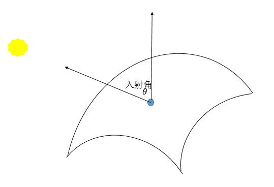
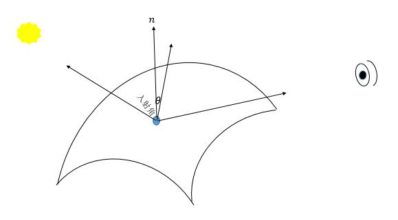
散射光:从物体表面向全方位360度均匀反射的光,代表了现实世界中粗糙物体表面被光照射时,反射到各个方向基本均匀,也被称为漫反射。散射光强度和入射角关系很大,入射角度越小,越亮。
散射光最终强度=散射光强度∗max{0,(cosθ)}
其中θ表示入射角
散射光的示意图
接下来主要修改顶点设色器的代码即可。
private String vertexShaderCode = "uniform mat4 uMVPMatrix;"
      + "uniform mat4 uMMatrix;" // 模型变换的矩阵
      + "uniform vec3 uLightLocation;" // 光源位置
      + "attribute vec4 aColor;"
      + "varying vec4 vColor;"
      + "varying vec4 vDiffuse;" // 传递给片元着色器的散射光强度,需要插值计算
      + "attribute vec3 aPosition;" // 顶点位置
      + "void main(){"
      + "vec3 normalVectorOrigin = aPosition;" // 原始采用点法向量
      + "vec3 normalVector = normalize((uMMatrix*vec4(normalVectorOrigin,1)).xyz);" // 归一化的变换后的法向量
      + "vec3 vectorLight = normalize(uLightLocation - (uMMatrix * vec4(aPosition,1)).xyz);" // 归一化的光源到点的向量
      + "float factor = max(0.0, dot(normalVector, vectorLight));"
      + "vDiffuse = factor*vec4(1,1,1,1.0);" // 散射光强度,需要插值计算
      + "gl_Position = uMVPMatrix * vec4(aPosition,1);"
      + "vColor = aColor;"
      + "}";
片元着色器
private String fragmentShaderCode = "precision mediump float;"
      + "varying vec4 vColor;"
      + "varying vec4 vDiffuse;" // 从顶点着色器传过来的插值散射光的值,散射光的值依赖顶点。
      + "void main(){"
      + "gl_FragColor = vColor*vDiffuse;" // 原本的颜色乘上散射光强度
      + "}";
上面主要的代码含义已经添加在注释里面了。还有以下几个地方需要注意
接着修改顶点和片元着色器后,再在代码中增加获取uMMatrix、uLightLocation的引用以及往着色器传递数据的代码
muMMatrixHandle = GLES20.glGetUniformLocation(mProgram, "uMMatrix");
muLightLocationHandle = GLES20.glGetUniformLocation(mProgram, "uLightLocation");
...
GLES20.glUniformMatrix4fv(muMMatrixHandle, 1, false, mMatrix, 0);
GLES20.glUniform3f(muLightLocationHandle, 0, 0, 20);

 // 注意和摄像机位置的设置,否则设置到背面就只能看见一点点内容了
增加了散射光的效果,可以看到效果明显好了很多,有些地方比较暗,有些地方就是黑的,因为光照没有照上。因为散射光根据和光源的角度有关,角度越小越亮,这就是自然界的真实现象。
镜面光
镜面光:现实世界中,当光滑表面被照射后会有方向很集中的反射光,这种反射光就是镜面光,镜面光除了依赖入射角外,还依赖观察者(摄像机)的位置,如果摄像机到被照射点的向量不在反射光集中的范围内,就看不到镜面光。
镜面光最终强度=镜面光强度∗max{0,(cosθ)α}
其中θθ指的是半向量和法向量的夹角,αα表示粗糙度。
镜面光示意图
使用镜面光时,需要将摄像机矩阵传入顶点着色器中,计算方法只需要按照定义来就可以。
综合环境光、散射光和镜面光的模型
gl_FragColor = vColor*vec4(0.5,0.5,0.5,1) + vColor*vDiffuse + vColor*vSpecular